DAL-SIM-900 : LVDT Simulator
Voltage controlled testing of LVDT measurement electronics

Product Description
The DAL-SIM-900 simulates LVDT secondary signals for electrical verification of signal conditioners, displacement acquisition systems and automated test equipment. A 0 to 10 V DC command sets the simulated position through complementary VA and VB outputs with a shared CT terminal, enabling multipoint checks without moving a physical sensor.
The simulator operates from a nominal 24 V DC supply and uses an external 3 kHz, 4.25 Vrms sine-wave excitation. Its nominal normalized output ratio covers −0.9 to +0.9, with a nominal combined secondary amplitude of 4.0 Vrms.
Ratiometric acquisition evaluation • Troubleshooting of LVDT signal conditioner.
Nominal conditions: 24 V DC supply; external 3 kHz, 4.25 Vrms sine wave measured at the excitation input with the simulator connected.
Result referenced to the straight line between endpoints and a full ratio span of 1.8. This is not a guaranteed accuracy limit; it excludes endpoint gain and offset error.
The 4.0 Vrms amplitude sum is nominal at the stated excitation; it is not an exact constant or a regulated-output guarantee for other excitation conditions. Ratio nonlinearity describes departure from an endpoint straight line and must not be interpreted as total system accuracy.
Performance depends on excitation, connected load and command-source quality. Mechanical travel is not assigned: the equipment under test determines the displacement scale associated with the simulated ratio.
Signal names identify functions, not connector pin numbers. Use the confirmed product connection drawing when wiring the unit.
The specified function is LVDT secondary-amplitude simulation. Resolver modes, programmable phase shift and open-circuit or short-circuit fault insertion are outside the specified feature set. Output loading, supply tolerance, temperature range, settling time, phase error and isolation ratings require confirmation for the intended application.
We also accept customized requirement for LVDT simulator.
The simulator operates from a nominal 24 V DC supply and uses an external 3 kHz, 4.25 Vrms sine-wave excitation. Its nominal normalized output ratio covers −0.9 to +0.9, with a nominal combined secondary amplitude of 4.0 Vrms.
1. Key features
• Standard 0–10 V command for manual or automated test sequences
• Three-terminal VA / CT / VB secondary interface
• Complementary outputs for negative, zero and positive simulated positions
• External excitation reference for connection to compatible LVDT electronics
• Three-terminal VA / CT / VB secondary interface
• Complementary outputs for negative, zero and positive simulated positions
• External excitation reference for connection to compatible LVDT electronics
2. Functional interface
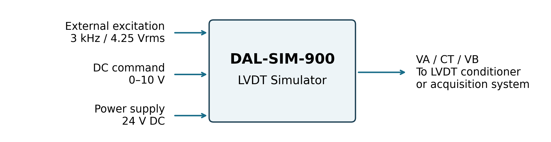
The diagram shows external functions only. Signal names identify connection functions; final connector assignments are supplied with the product.
3. Nominal output characteristics
Increasing the command raises VA and lowers VB. At 5 V, both amplitudes are nominally 2.0 Vrms and the ratio is zero.
| DC command | VA to CT | VB to CT | Normalized ratio |
| 0 V | 0.200 Vrms | 3.800 Vrms | −0.900 |
| 5 V | 2.000 Vrms | 2.000 Vrms | 0.000 |
| 10 V | 3.800 Vrms | 0.200 Vrms | +0.900 |
4. Applications
Zero and span verification • Automated multipoint verification of LVDT signal conditioners • Production testing.Ratiometric acquisition evaluation • Troubleshooting of LVDT signal conditioner.
5. Technical specifications
Nominal conditions: 24 V DC supply; external 3 kHz, 4.25 Vrms sine wave measured at the excitation input with the simulator connected.
| Parameter | Value or Description |
| Simulation channels | One LVDT channel with two complementary secondary outputs |
| Sensor signal configuration | Two excitation connections and three secondary connections (VA / CT / VB) |
| Supply voltage | 24 V DC nominal |
| DC command input | 0 to 10 V, referenced to signal GND |
| Excitation input | 3 kHz, 4.25 Vrms sine wave nominal, excitation frequency can change |
| Control method | External analog command; a programmable DC source can automate test points |
| Secondary output interface | VA / CT / VB, shared secondary common |
| Normalized ratio range | −0.9 to +0.9 nominal |
| Secondary amplitude range | 0.2 to 3.8 Vrms per channel, nominal |
| Secondary amplitude sum | VA + VB = 4.0 Vrms nominal |
| Ratio nonlinearity¹ | Max 0.01% of the full ratio span |
Result referenced to the straight line between endpoints and a full ratio span of 1.8. This is not a guaranteed accuracy limit; it excludes endpoint gain and offset error.
6. Command and ratio relationship
For command U in volts and RMS amplitudes VA and VB measured relative to CT, the nominal relationships at the specified excitation are:
R = (VA − VB) / (VA + VB) = 0.18U − 0.90
VA = 0.20 + 0.36U Vrms
VB = 3.80 − 0.36U Vrms
VA and VB are RMS amplitudes measured relative to CT. These amplitudes define the ratio; a true-RMS reading directly between VA and VB does not by itself establish the signed ratio. Output polarity and phase compatibility must be checked with the connected instrument.
R = (VA − VB) / (VA + VB) = 0.18U − 0.90
VA = 0.20 + 0.36U Vrms
VB = 3.80 − 0.36U Vrms
7. Specification notes
The 4.0 Vrms amplitude sum is nominal at the stated excitation; it is not an exact constant or a regulated-output guarantee for other excitation conditions. Ratio nonlinearity describes departure from an endpoint straight line and must not be interpreted as total system accuracy.Performance depends on excitation, connected load and command-source quality. Mechanical travel is not assigned: the equipment under test determines the displacement scale associated with the simulated ratio.
8. Signal connections
| Signal | Connection function |
| 24 V DC power input | Connect the designated supply positive and return terminals. |
| EXC_P / EXC_N | Connect a compatible external excitation source, including the equipment under test where suitable. |
| ADJ_DC_IN / signal GND | Connect the 0–10 V command source and its return. |
| VA | Secondary A output; amplitude measured relative to CT. |
| CT | Shared secondary common; separate from the DC command return. |
| VB | Secondary B output; amplitude measured relative to CT. |
Signal names identify functions, not connector pin numbers. Use the confirmed product connection drawing when wiring the unit.
9. Connections and operation
1. Connect the nominal 24 V DC supply to the designated power input.
2. Connect a compatible excitation source to EXC_P / EXC_N and verify the loaded amplitude.
3. Connect the command source to ADJ_DC_IN and signal GND.
4. Connect VA / CT / VB to the secondary input of the equipment under test.
5. Verify the 0 V, 5 V and 10 V command points, then run the required test sequence.
CT is the secondary common, not the DC command return. Use signal GND for the command source. The simulator verifies electrical measurement channels; it does not reproduce a physical sensor’s mechanical behavior.
2. Connect a compatible excitation source to EXC_P / EXC_N and verify the loaded amplitude.
3. Connect the command source to ADJ_DC_IN and signal GND.
4. Connect VA / CT / VB to the secondary input of the equipment under test.
5. Verify the 0 V, 5 V and 10 V command points, then run the required test sequence.
CT is the secondary common, not the DC command return. Use signal GND for the command source. The simulator verifies electrical measurement channels; it does not reproduce a physical sensor’s mechanical behavior.
10. Compatibility and selection
Specify the conditioner model, excitation voltage and frequency, secondary wiring, input load and required test speed when ordering. The VA / CT / VB interface addresses a shared-common secondary configuration; compatibility with other wiring arrangements requires confirmation. A standard DC PLC input requires an LVDT conditioner between it and the simulator.The specified function is LVDT secondary-amplitude simulation. Resolver modes, programmable phase shift and open-circuit or short-circuit fault insertion are outside the specified feature set. Output loading, supply tolerance, temperature range, settling time, phase error and isolation ratings require confirmation for the intended application.
We also accept customized requirement for LVDT simulator.