3SL24-60: Three-Channel LVDT Position Sensor and Signal Conditioner
±60 mm travel • Three 0–5 V outputs • 28 V DC supply
Product Description
1. Key features
2. System configuration
3. Three channels, one motion
4. Ratiometric conditioning and remote electronics
5. Typical applications
6. Sensor performance
7. Power, excitation and outputs
8. Mechanical and environmental
9. Connection essentials
10. System performance and ordering
- Three mechanically coupled LVDT channels in one Ø24 mm housing
- ±60 mm electrical travel (120 mm total range)
- Sensor nonlinearity and channel tracking error: ±0.3% FS maximum
- Crosstalk <0.1% FS; null voltage ≤10 mVrms
- Three-channel conditioner with individual 0–5 V outputs
- 28 V DC supply; separate channel excitation frequencies; 100 Hz bandwidth
- Sensor rated −40 to +125 °C; 1 MPa withstand with full immersion in kerosene
- Braid-shielded leads for each channel; external electronics for remote mounting
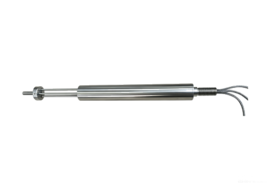
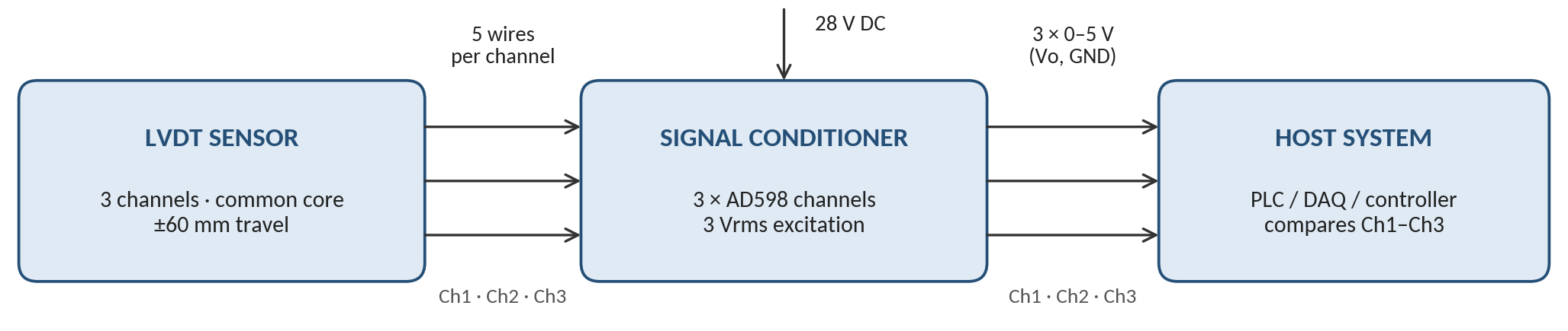
The 3SL24-60 measures one linear displacement with three mechanically coupled LVDT channels. An external conditioner excites each channel and converts its secondary signals into a separate 0–5 V DC position output. A host controller or data acquisition system reads the three outputs for position feedback and channel comparison.
2. System configuration
3. Three channels, one motion
The three channels follow the same coupled movement, so the host can compare Ch1–Ch3 for plausibility checks. Separate excitation frequencies per channel help limit interference between channels. Fault-detection thresholds and voting logic are implemented in the host controller; electrical isolation and fault containment require configuration-specific confirmation.
4. Ratiometric conditioning and remote electronics
Each channel processes the secondary amplitude ratio (VA − VB)/(VA + VB) and scales it to a position output. External electronics permit remote installation; the sensor’s temperature and immersion ratings do not apply to the conditioner.
5. Typical applications
|
|
Technical specifications
Reference conditions: 28 V DC supply and 3 Vrms excitation, unless stated.
Reference conditions: 28 V DC supply and 3 Vrms excitation, unless stated.
6. Sensor performance
| Parameter | Specification |
| Channels | 3 LVDT channels, common mechanical motion |
| Electrical travel | ±60 mm (120 mm total) |
| Sensor nonlinearity | ±0.3% FS maximum¹ |
| Channel-to-channel crosstalk error | ±0.1% FS maximum¹ |
| Null (residual) voltage | ≤10 mVrms |
| Sensor interface | 5 wires per channel: E+, E−, VA, CT, VB |
7. Power, excitation and outputs
| Parameter | Specification |
| DC supply | 28 V DC nominal; one shared power input |
| Supply current | 130 mA maximum |
| Excitation | 3 Vrms; 2.5 kHz / 2.6 kHz / 2.7 kHz |
| Analog outputs | 3 × 0–5 V DC, one per channel (Vo / GND) |
| Output characteristic | −60 mm → 0 V; 0 mm → 2.5 V; +60 mm → 5 V |
| Nominal bandwidth | 100 Hz |
8. Mechanical and environmental
| Parameter | Specification |
| Sensor body | Ø24 mm (+0 / −0.1) × 200 mm |
| Rear mounting | M12 × 1-6h thread; 33 mm rear section |
| Moving end | 3 × Ø3 mm rods; Ø22 mm coupling; M6 stud; null projection 60 ±0.5 mm |
| Leads | 500 mm; 5 conductors per channel; braid shield on each channel |
| Operating temperature (sensor) | −40 to +125 °C |
| Pressure withstand | 1 MPa, complete sensor immersed in kerosene |
| Conditioner enclosure | Metal; 108 × 95 × 30 mm |
| Conditioner weight | 200 g |
Sensor outline, dimensions in mm; schematic, not to scale
FS (full scale) is the 5 V output span, equal to 120 mm of travel
Nominal mapping. Use the approved installation drawing to identify positive motion, and calibrate each channel after installation.
Setup and integration
FS (full scale) is the 5 V output span, equal to 120 mm of travel
Nominal mapping. Use the approved installation drawing to identify positive motion, and calibrate each channel after installation.
Setup and integration
9. Connection essentials
Repeat the connections for Ch1, Ch2 and Ch3. VA and VB are AC secondary connections; CT is the secondary center tap, not an output ground. Connect the 28 V DC supply to +28V and its return to 0, and measure each output between Vo and its GND terminal. Confirm the common-ground arrangement before interconnecting returns.
| Lead colour | Function | Conditioner terminal |
| Red | Primary excitation + | E+ |
| Blue | Primary excitation − | E− |
| Yellow | Secondary coil A | VA |
| White | Secondary center tap | CT |
| Black | Secondary coil B | VB |
| Shield | Channel cable shield | Ground, per approved terminal drawing |
The X terminals are not assigned in this datasheet, leave them unconnected.
10. System performance and ordering
Overall accuracy depends on the sensor, conditioner, cable, load, temperature and calibration device. Verify each installed channel over its intended travel and operating conditions.
Specify 3SL24-60, measuring travel (±60 mm), output and load requirements, lead length (500 mm standard), mounting and coupling arrangement, operating environment, excitation frequency allocation and any calibration data required.
Specify 3SL24-60, measuring travel (±60 mm), output and load requirements, lead length (500 mm standard), mounting and coupling arrangement, operating environment, excitation frequency allocation and any calibration data required.